| Adding a Stake Point in Edit Mode |
|
|
|

|
|
|
|
|

|
- Select the Stake List Mode icon. The Stake List Editor will display. The Stake List Editor is used to add the desired points to the Stake List. The Stake List Editor is a floating window, which may be moved to a secondary monitor, or may be docked to the side of the screen. You may also change the Surface and Layer when the Stake List Editor is open.
|
|
|
|
|
|
|
|
|
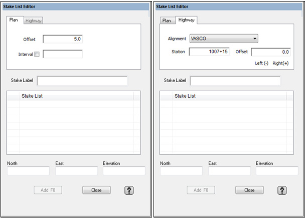
- Plan mode is used when creating a stake list from a Sitework project. Plan mode displays Offset and Interval. Highway mode is used when creating a stake list from data generated in Highway mode. Highway mode displays Station and Offset.
|
| Plan Mode |
|
|
|
|
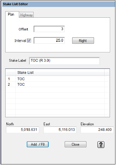
- Enter the desired offset distance. This distance applies to all offset guides. Check Interval to add points along, or offset from the selected line. Enter the desired interval. Left click on a data line to select the desired point or line. The northing, easting and elevation of the selected point will display at the bottom. Click Add to add the selected point to the Stake List. If Interval is checked, click Add to add all the points to the list.
|
|
|
|
|
|
|
|

|
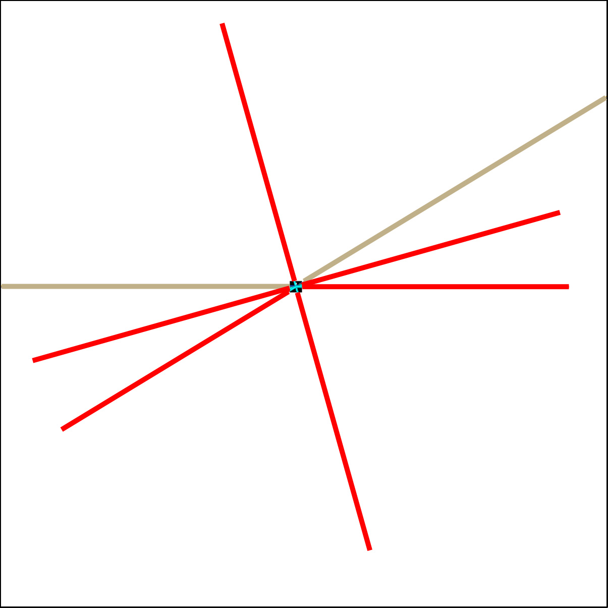
- The offset stake guides will display in red projecting from the selected point. To add an offset stake, point to the end of the desired offset guide and press the F8 key on the keyboard to add the point to the stake list. There are several options depending on the properties of the selected point.
|
|
|
|

|
- When the end of a line is selected, the offset stake guides will project perpendicular left and right, as well as in line with the last segment of the line.
|
|
|
|

|
- When a point is selected on a straight line, the offset stake guides will project perpendicular to the left and right sides of the line. The in line offsets should follow the direction of the line.
|
|
|
|

|
- When a point is selected on a 90 degree corner, the offset stake guides will project perpendicular to the adjacent sides, as well as a 45 degree offset from the corner. Single points are displayed at the corner of the box (5 x 5, 10x 10, etc).
|
|
|
|
|
- When a point is selected on an angle point, the offset stake guides bisect the angle between the two segments on either side of the selected point, as well as projecting in the same direction as the two adjacent segments.
|
|
|
|

|
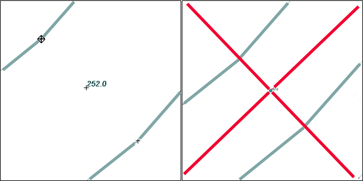
- When selecting a single point, the offset stake guides will project North/South and East/West. To create a user defined angle, hold the ALT key and select the base point to be used to create the desired angle.
|
|
|
|
|
|
|
|
|
|
|
- A diamond will display on the point. Release the ALT key and select the single point. The offset stake guides will project perpendicular and in line with the desired angle. This also applies to angle points if you want offsets perpendicular to the adjacent segments.
|
|
|
| Highway Mode |
|
|
|
|
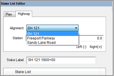
- When adding stake list points to a highway file, you must first select the desired alignment.
|
|
|
|
|
|
|
|
|
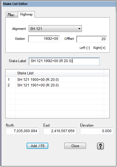
- The stake points are based on station and offset. Left click to select the desired point. The station number will display. Enter the desired offset. Click the Add button to add the point to the Stake List. You may also enter the station number manually.
|
|
|
|
|
|

|
|
|
|
|
| Adding a Stake Point in Entry Mode |
|
|
|

|
|
|
|
|
|
- Change the Layer to Stake List Points.
|
|
|
|

|
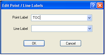
- Enter a label for the stake by pressing the Point button on the lower left part of the Elevation window to display the Edit Point / Line Labels window.
|
|
|
|
|
|
|
|
|
- Type in a label for the stake point in the Point Label text box. Press OK to continue.
|
|
|
|
|
- Using the Left Mouse button, enter in the stake point. Using Snap allows you to snap the stake points to existing points. To change the label for a different stake point, press the Right Mouse button to end data entry, then press the Line button and change the label.
|
![]()