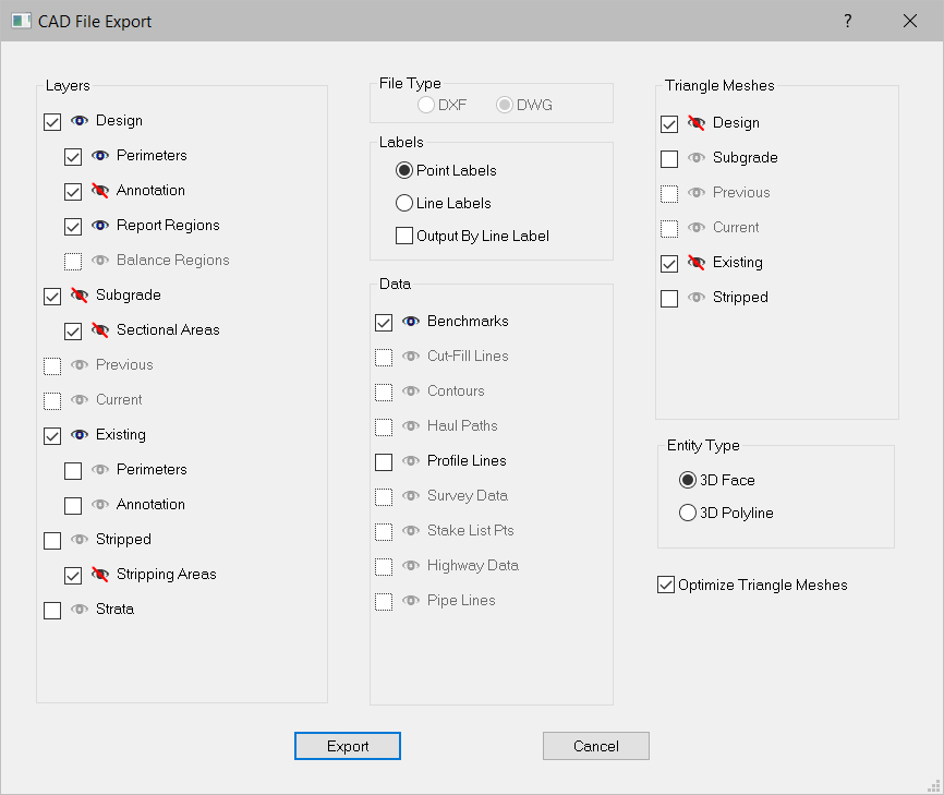
The DXF/DWG export is quite powerful and has many options. When selected the CAD File export window displays.

The export choices are broken down by Surface, Data, and Triangular Meshes. The type of file saved is chosen by checking either DXF or DWG.
When exported, each checked option is created in the DXF/DWG as a separate layer. Descriptions of the three option types are written below.
Layers may be included in the file, however the default layer visibility may be controlled by clicking the Visibility icon. A red slash will indicate the layer will be included, however it will not be turned off when opening the file.. .
Surface options are the data lines displayed as the overlay and create the three-dimensional views (annotation is an exception). Many of these are self-explanatory.
Design |
Design surface data lines. |
Perimeter |
The proposed perimeter line. |
Annotation |
Annotation in the Design surface. |
Report Regions |
Areas selected for individual reporting. |
Balance Regions |
Haul Path and Balance Region boundary. See Balance Regions |
Subgrade |
The subgrade surface is the design surface data lines lowered by the Sectional Area depth. |
Sectional Areas |
The line(s) that describe the area sections are applied Areas to. |
Previous |
Data Lines from the Previous Surface |
Current |
Data Lines from the Current Surface |
Existing |
Existing ground surface data lines. |
Perimeters |
The existing ground perimeter line. |
Annotation |
Any annotation lines present in the existing surface data. |
Stripped |
The stripping surface is the existing ground surface data lines lowered by the Stripping Area depth. |
Stripping Areas |
The line(s) that describe the area to be stripped. |
Strata |
Sloping Break Lines connecting bore locations. |
The Label options allow you to select the type of label to be exported.
Point Labels |
The text labels entered on points. |
Line Labels |
The text labels entered on lines. |
Output by Label |
Uses line labels for the CAD layer names |
The Data options are a miscellaneous category where the choices do not necessarily fit into any other layer. Each option when checked is written as a separate layer.
Benchmarks |
Any Benchmark points display as a plus across a circle. |
Cut/Fill Lines |
Lines created at a user selected Cut/Fill boundary. See Cut-Fill Lines |
Contours |
Lines created using the Contour Surface command. |
Haul Path |
Lines generated in the Haul Path layer. |
Profile Lines |
Lines created in Profile mode. |
Survey Data |
Data entered in Survey Data layer. |
Stake List Pts |
Points entered (with or without labels) for use in Graphic Grade |
Highway Data |
Data generated from surfacing highway data. |
Pipe Lines |
Data entered in the Pipe Lines layer. |
Triangular Meshes are three-dimensional triangles that the program creates based on the data lines of the different surfaces.
Entity Type allows the user to specify the way these meshes are written. The user should choose entity types based upon what the file is going to be read into and how it will be used.
After selecting the data to export, press the Export button. The file save window displays.

Name the file and press Save.