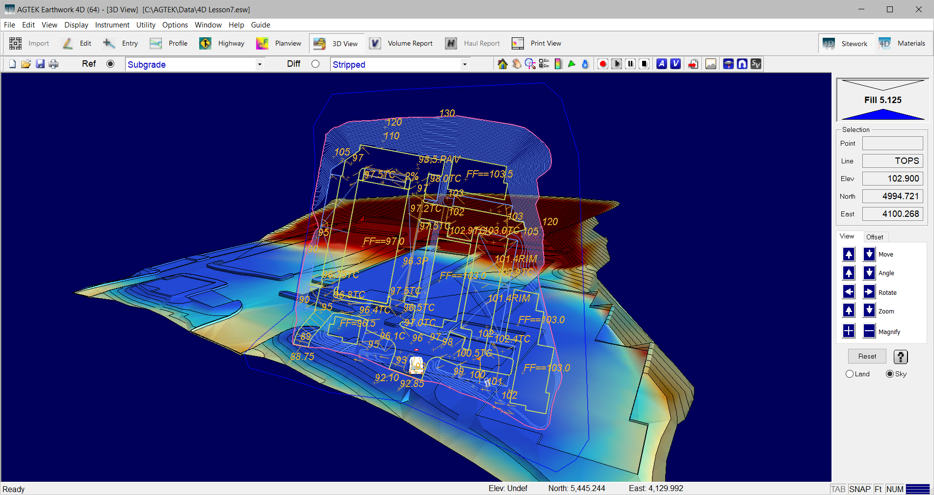
While the terrain shows how the program interprets data lines to form the surfaces in both Edit and Entry Mode, the 3D View window is a much more flexible version of the terrain which allows greater control over the view. The 3D View screen is similar to the Edit Window. The primary difference is the 3D controls replace the Elevation dialog and the toolbar adds a few icons.

Overlay |
The Overlay is the two-dimensional plan view of the data. In the 3D View clicking on the overlay moves the view to that position. The keyboard arrow keys move the 3D Terrain instead of panning the overlay. |
|
|
Terrain |
Terrain is the three-dimensional representation of a surface’s data lines color-coded by cut and fill. Purple-red represents Cut while green- blue represents fill. Areas displaying in yellow are close to the existing grade. |
|
|
Toolbars |
The Selection Toolbar shows the Reference surface and the Difference surface. The Terrain and Overlay (partially) views are determined and can be changed through the Reference Surface control. The Cut-Fill color is determined by comparing the Reference and Difference surfaces. Added to the Utility Toolbar are controls for creating a calculation boundary, calculating volumes, and playing back drive-throughs. You may add 3D Notes to the Documentation layer. Also see: Toolbars |
|
|
|
|
|
|
|
The Ref and Diff surfaces are used to compare different surfaces to one another in both the 3D View and when calculating the volumes. |