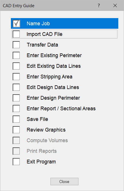
The CAD Entry Guide is designed to assist data entry from a CAD file. Press Guide on the menu bar and select CAD to display the CAD Entry Guide. Press the G key on the keyboard to activate the guide after selecting the desired guide. The suggested data entry sequence is listed from top to bottom on the list. Below is an explanation of the commands on the CAD Entry Guide.

Name Job |
Entry of job name, builder and data. Units of measure is only available on a new job. |
|
|
|
|
Import CAD File |
|
Import the desired CAD file. |
|
|
|
Transfer Data |
|
Transfer the selected CAD data to the desired surface and layer. |
|
|
|
Enter Existing Perimeter |
Switches to Entry Mode, Existing Surface, Perimeter Layer |
|
|
|
|
Edit Existing Data Lines |
|
Switches to Edit Mode, Existing Surface, Data Lines Layer |
|
|
|
Enter Stripping Areas |
|
Switches to Entry Mode, Existing Surface, Stripping Areas Layer |
|
|
|
Edit Design Data Lines |
Switches to Edit Mode, Design Surface, Data Lines Layer |
|
|
|
|
Enter Design Perimeter |
Switches to Entry Mode, Design Surface, Perimeter Layer |
|
|
|
|
Enter Report/Sectional Areas |
|
Switches to Entry Mode and starts the Add Report Regions command |
|
|
|
Save File |
|
Saves the current job. |
|
|
|
Review Graphics |
Switches to 3D View Mode |
|
|
|
|
Compute Volumes |
Calculates the volumes for the Design Perimeter and any Report Regions. |
|
|
|
|
Print Reports |
Switches to the Print Preview Page and send the Cut-Fill Shade Map and Volume Report to the Print Preview Page. |
|
|
|
|
Exit Program |
|
Exits the program. If job has changed since last save, you are prompted to save the job before exiting. |