Video Links: Reveal Maps Tutorial
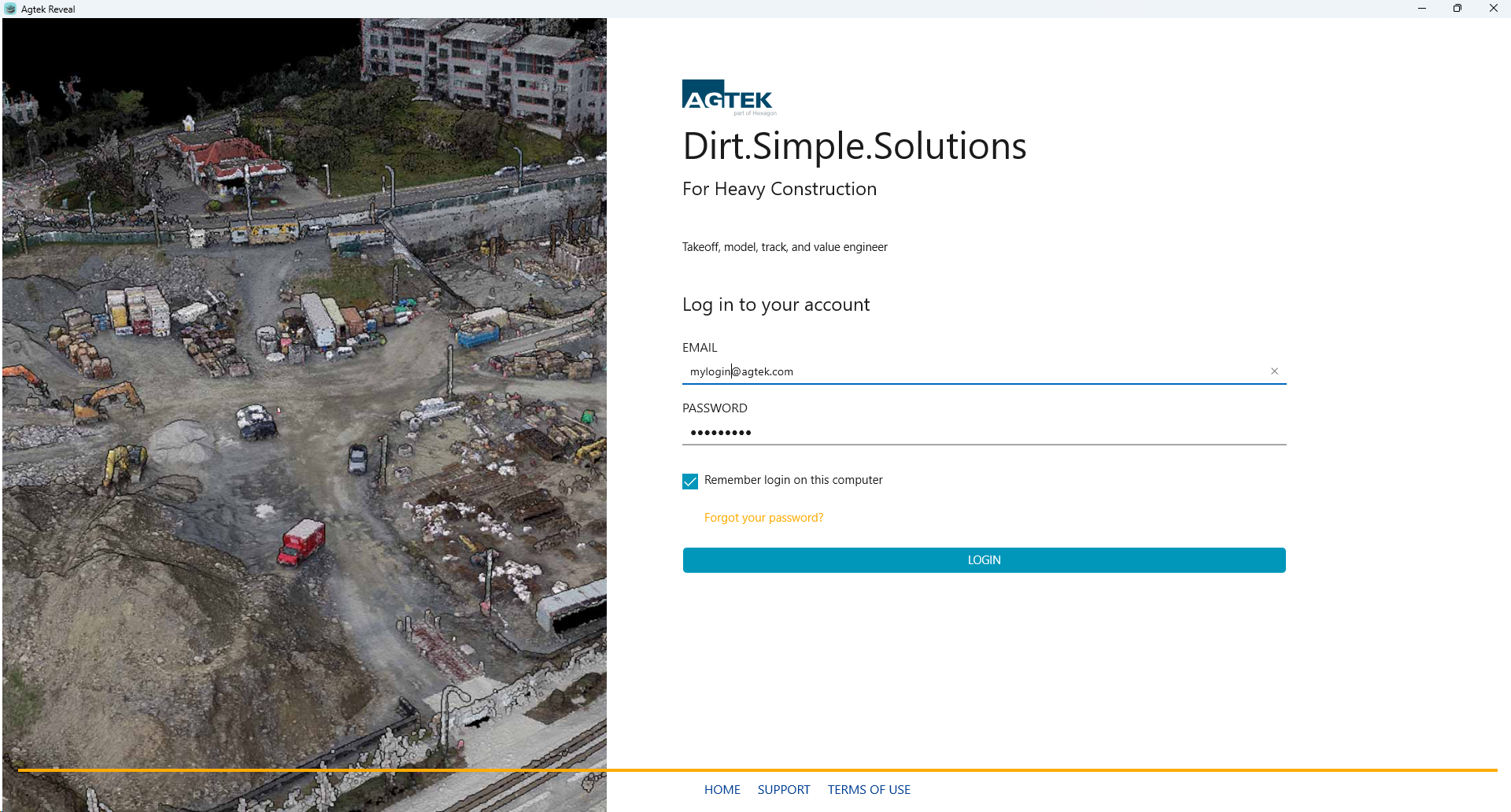
The Login window displays when logging into Reveal.
Enter your Email address and Password.
Click “Forgot your password?” if you need to reset a new password. A notification email will be sent to your registered user email. Follow the steps in the email.
Click the Remember login on this computer check box to remember your email and password for quicker access next time you open Reveal.
Click the “Login” button to continue.
Select the Home, Support, or Terms of Use links at the bottom of the page at anytime.
Select from the list of available license keys by clicking on one of the listed options.
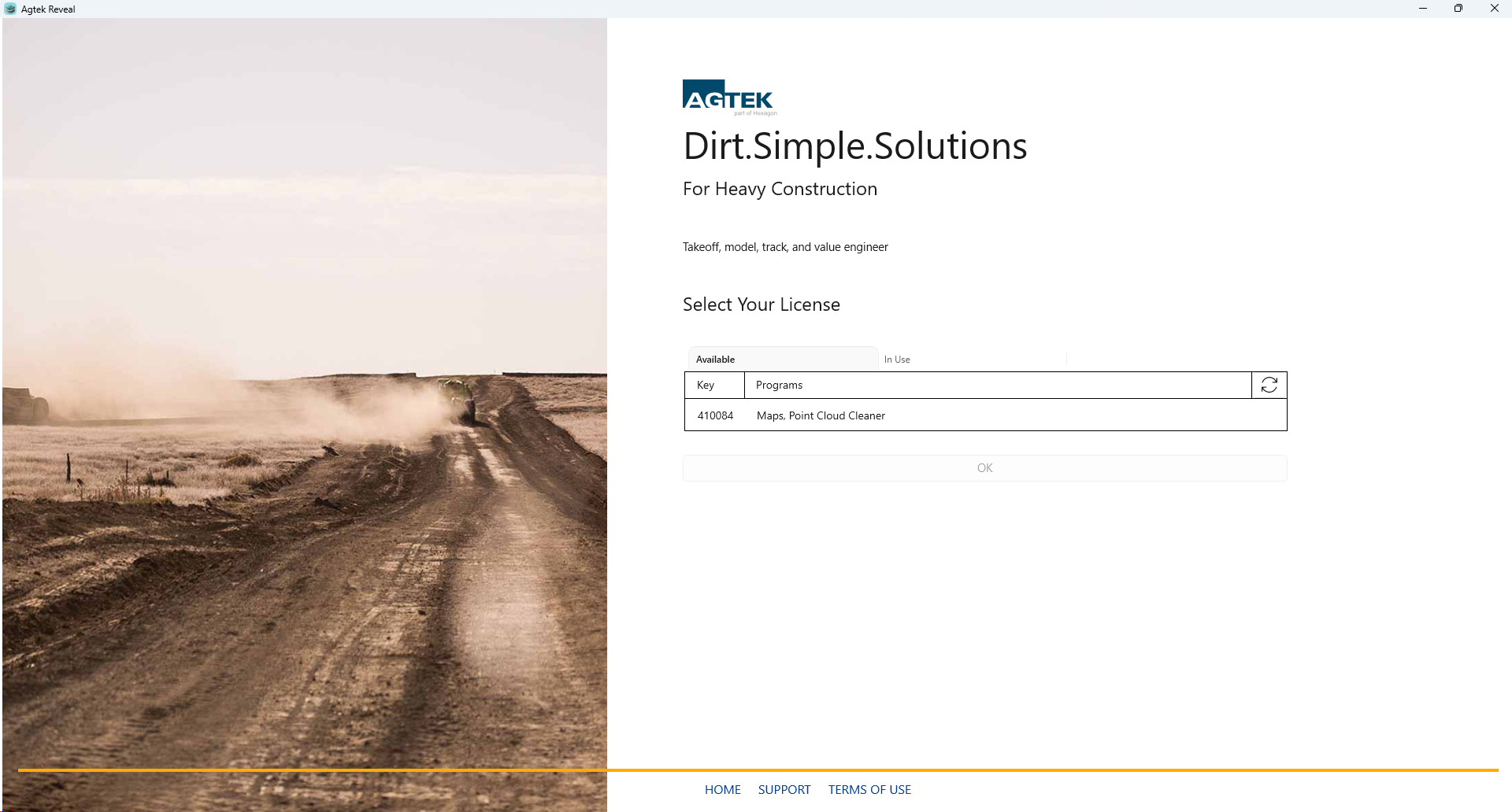
Click OK to continue
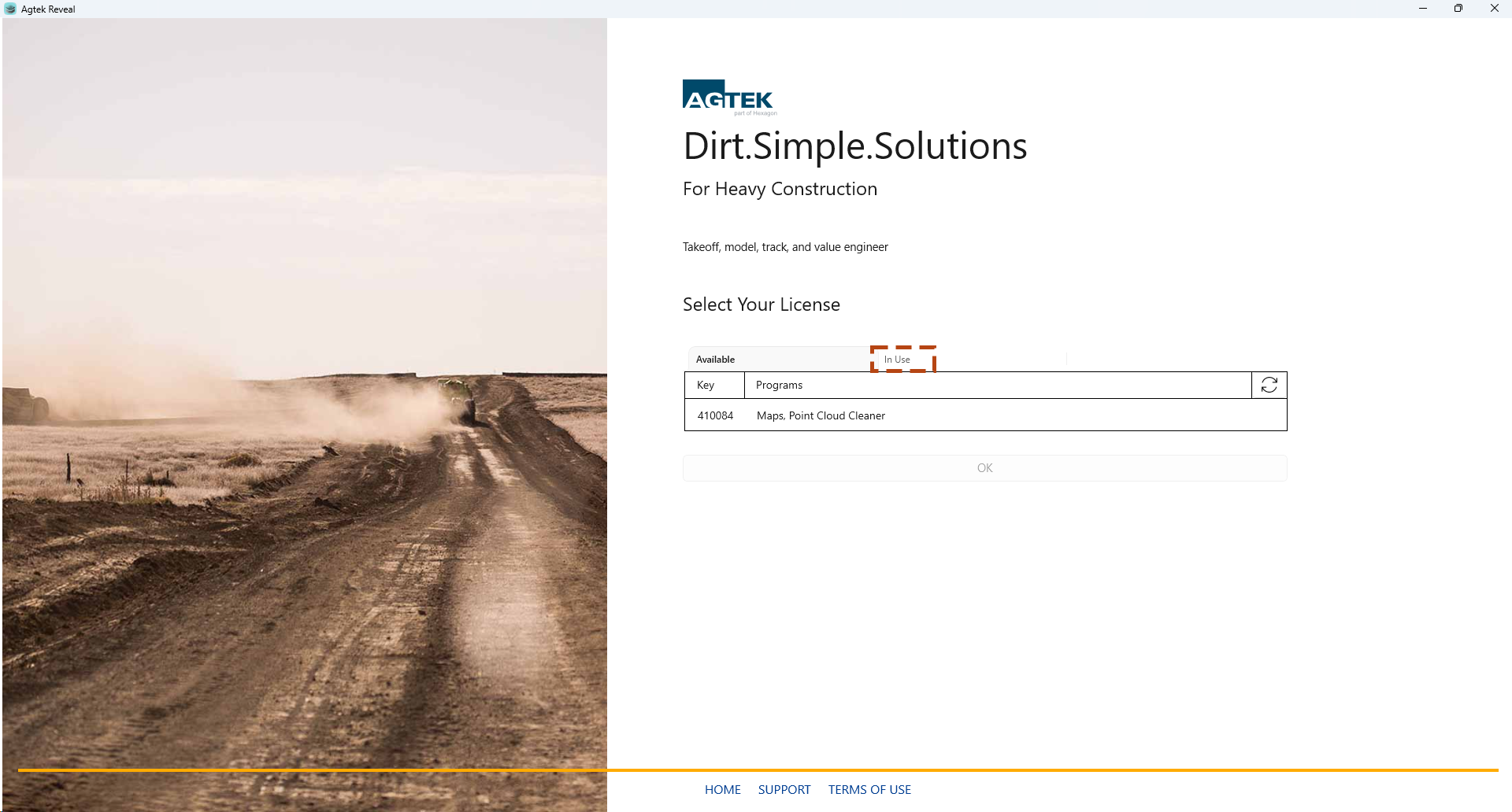
To view the In Use keys within your organization select the In Use tab.
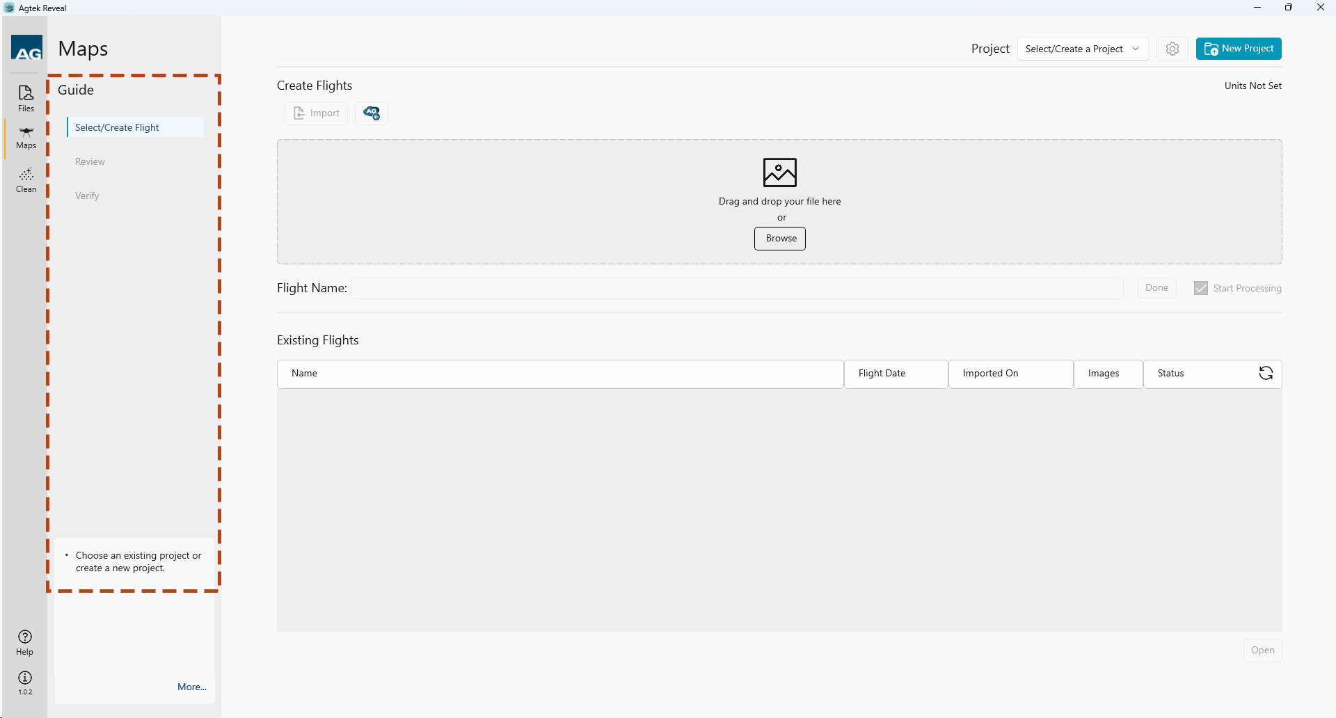
This screen introduces the Guide menu on the left side of your screen. The Guide is a dynamic menu that will walk you through the process from start to finish. Workflow steps are listed at the top. Helpful tips are shown at the bottom as you progress from start to finish.
New Project & Files
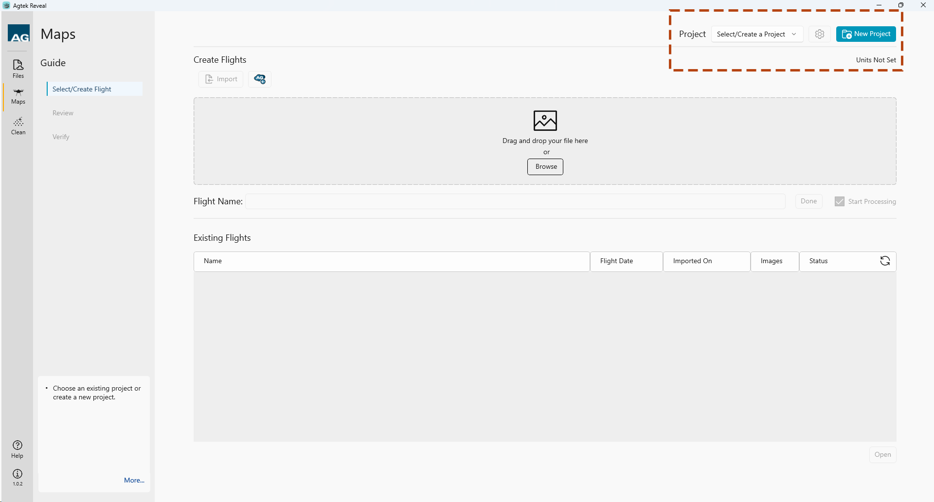
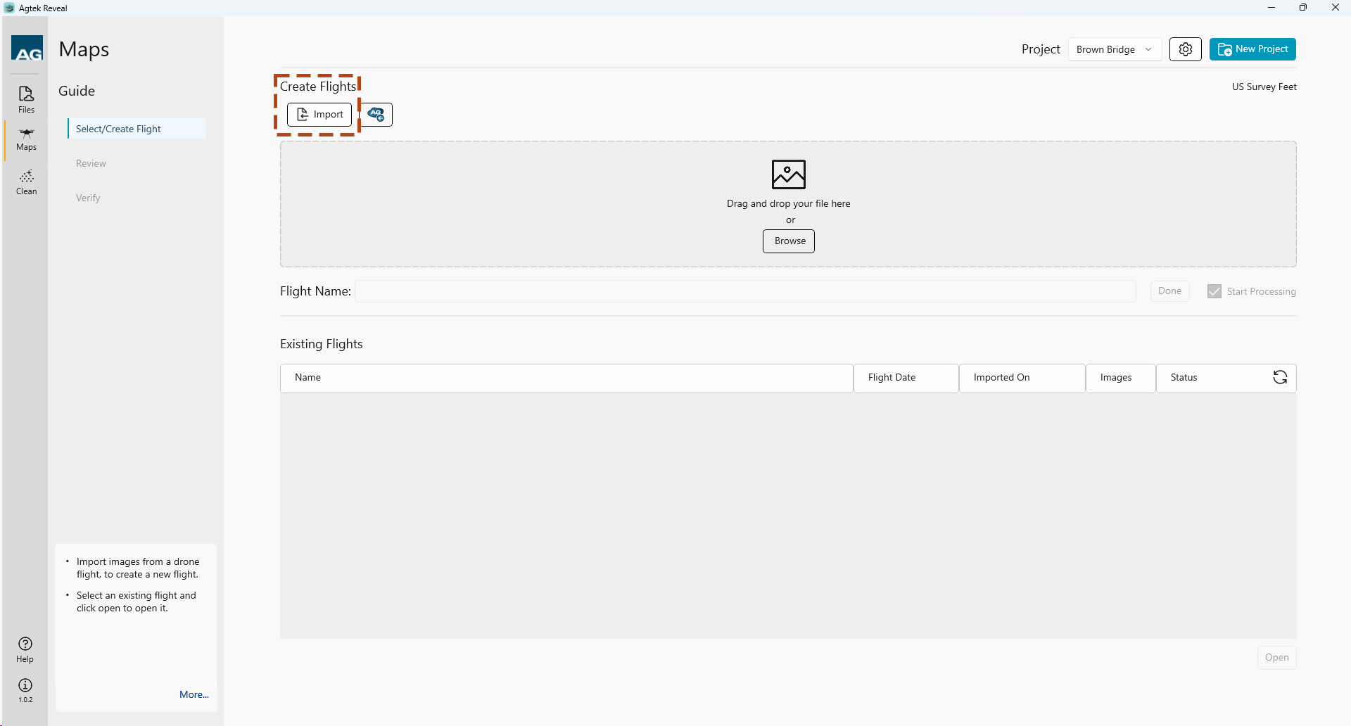
The New/Open Files menu is where you can create and manage your project settings.
To create a New Project, select the New Project button.
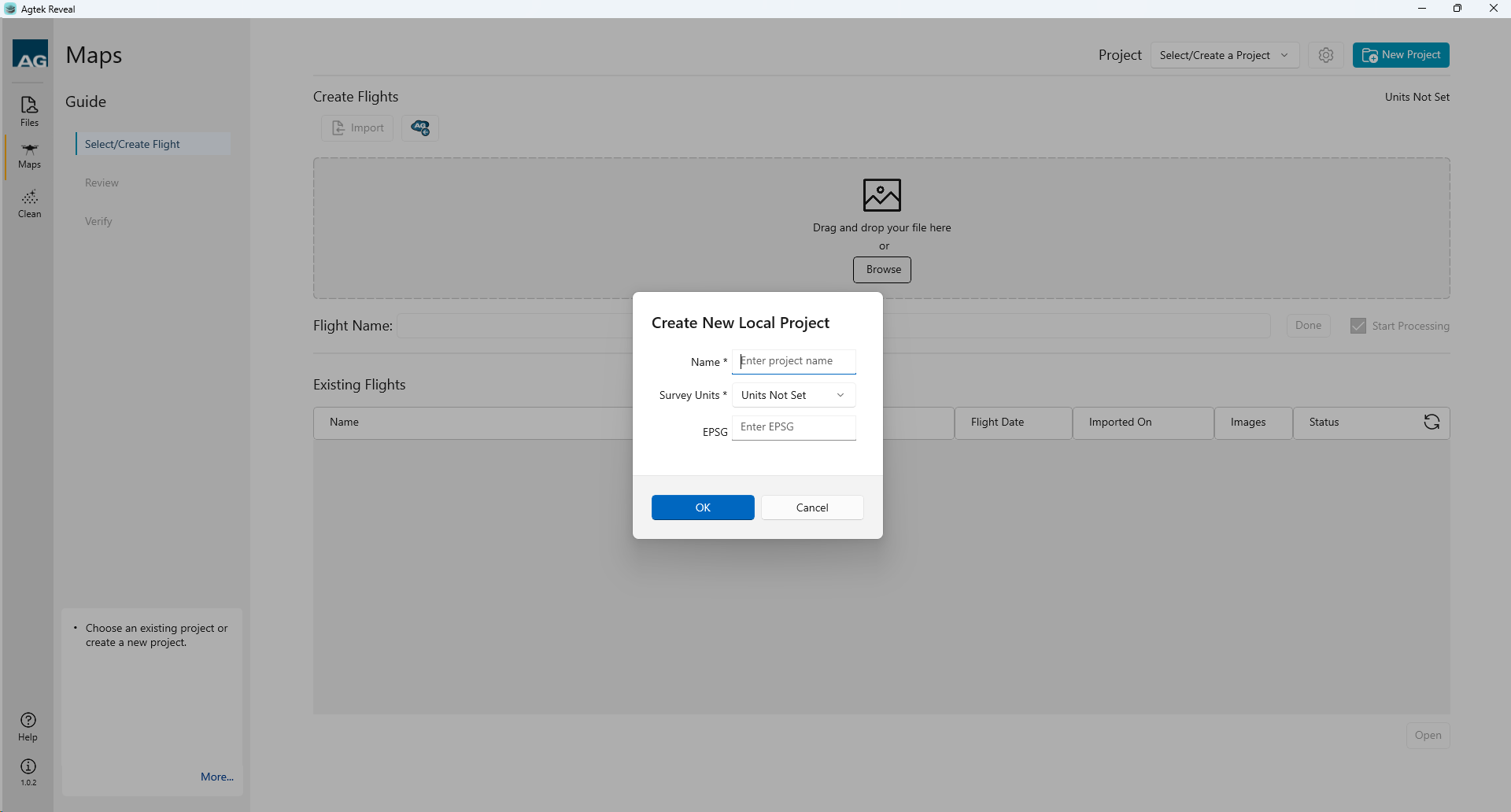
Name your project and select OK. Set the Survey Units. Enter the EPSG Code if known.
You may also select an existing Project from the drop down menu option.
Adjust your Project settings by selecting the Settings Icon.
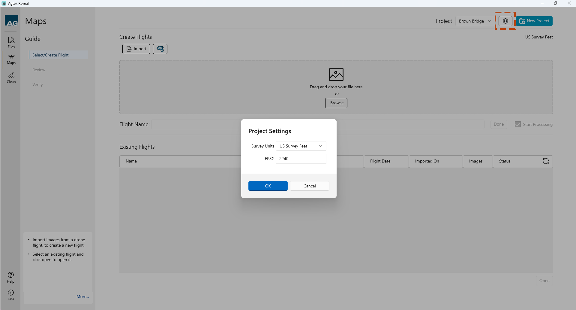
Within the Project Settings you can set the Units from the drop down menu.
The default Project foot definition is not defined. Reveal will look at the point cloud you upload for the selected project and update the Project foot definition to match.
Your project EPSG code can be entered as well.
Select OK when complete.
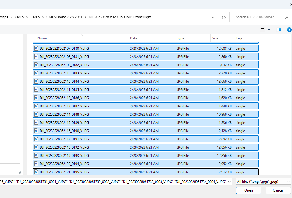
Reveal works with .jpg image file format.
You can import your photos into Reveal a couple ways.
1. Drag and drop your files.
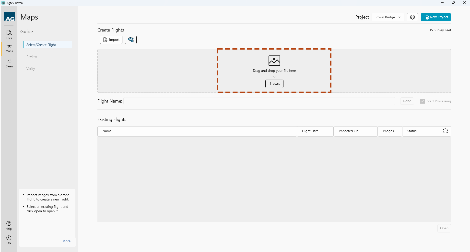
2. Browse for the photos on your machine.
Browse to the location of the photo images. Select all the files and click Open.
Upon selecting your Photos, Reveal Maps will import your files and display a name in the Flight Name menu.

Note:C
Check Start Processing to automatically begin processing the photos. Click Done.
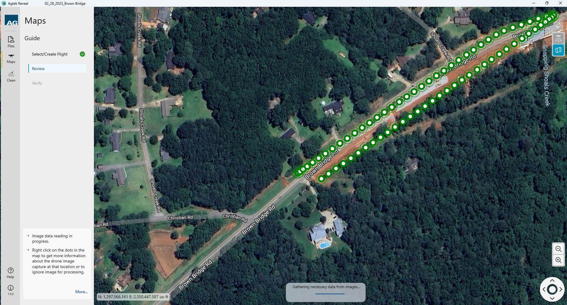
Reveal Maps will load and display the location of the photos. Processing will begin.
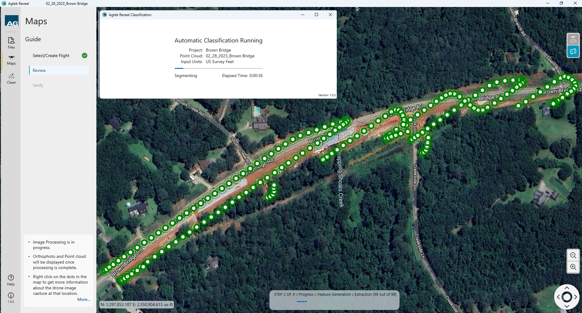
While processing the photos, the Classification will run simultaneously.
Note:
When the processing is complete, the ortho image will display.
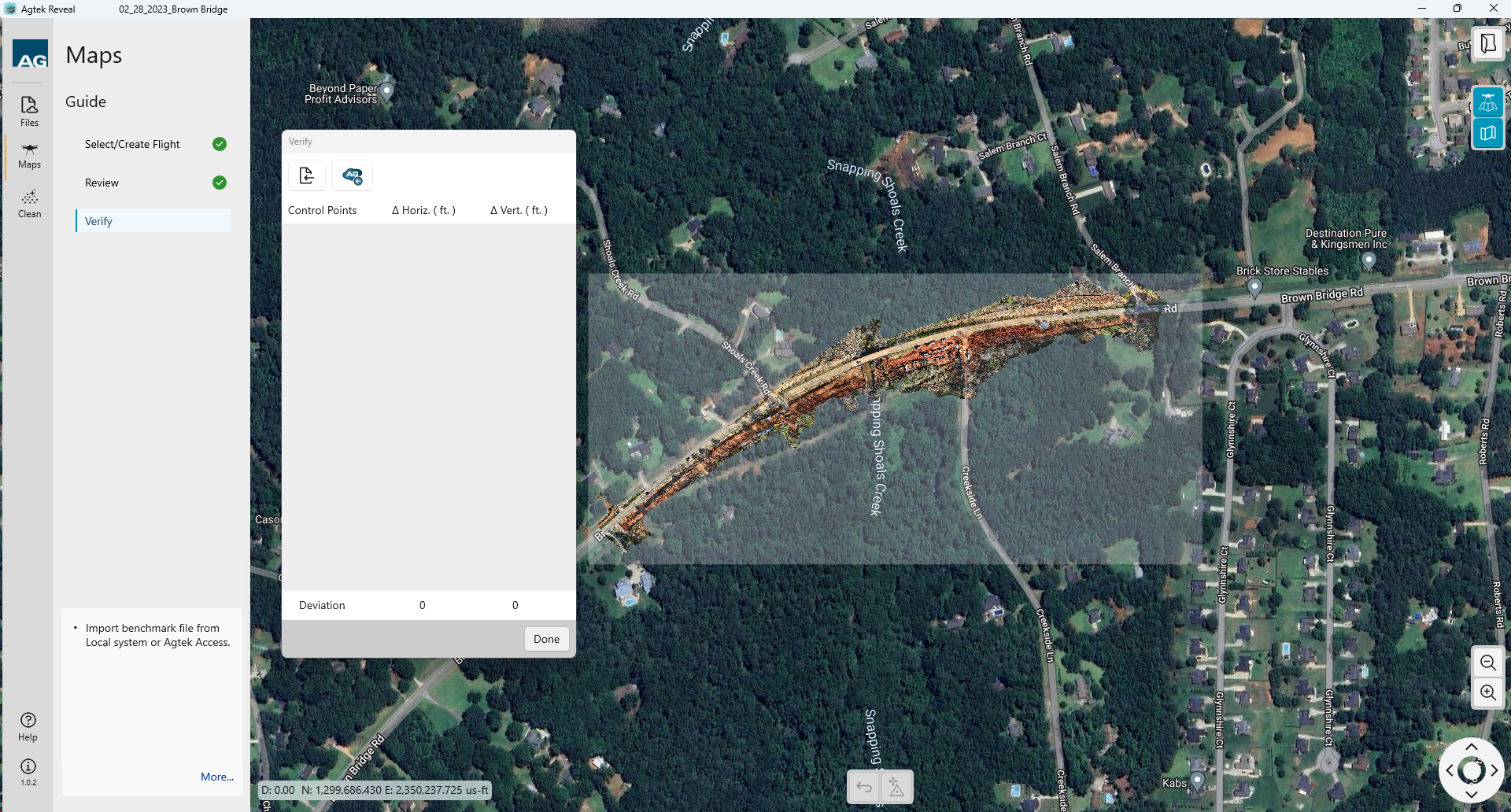
The Verify window will display. To begin, you will need the following:
Ground Control point file in one of the following formats:
ADF
3DR
PIX
AGI
DM
CSV (PNEZD)
Local (XYZ)
You can upload files from your local device or Agtek Access by selecting those buttons at the top of the dialog

Select the file type via the drop down menu.
Reveal accepts control point files from many photogrammetry engines as well as Agtek adf files. Select the format you would like to use.
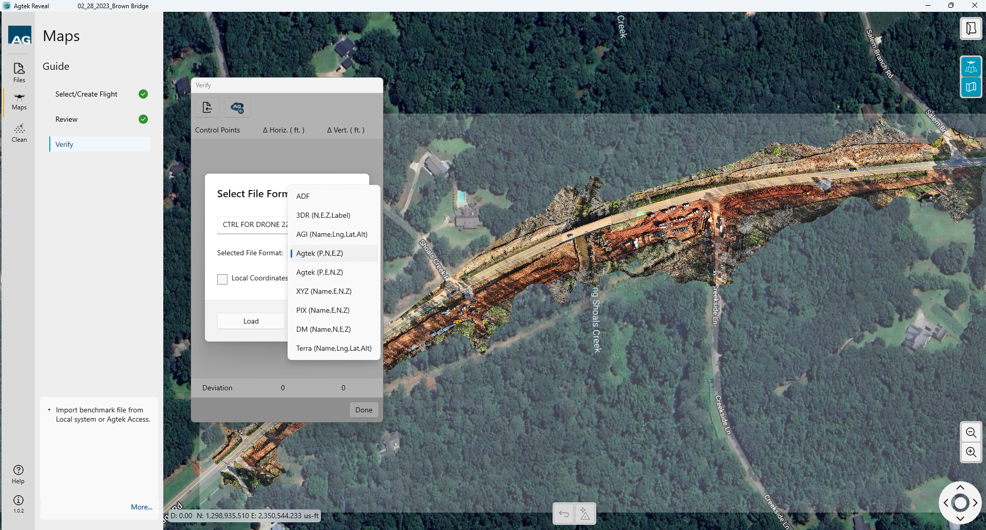
Upload your project control file by selecting the Load button. Your file name will appear once uploaded.
Once your control point file is uploaded you will see the point icons on your site.
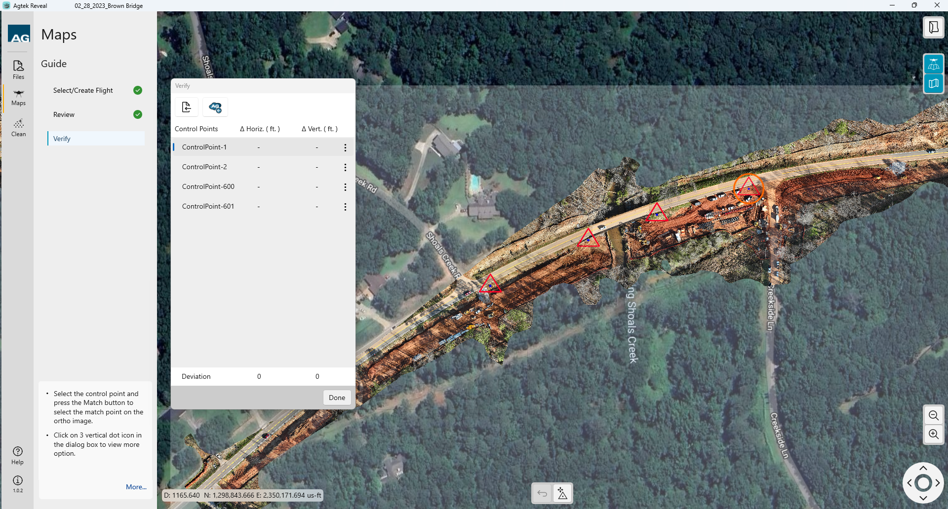
Finding your points
View your control point data by the following two methods prior to starting Verification.
Left clicking on any of the point icons will display the point attributes in the Verify dialog. This is purely informational and does not set your Verification.
Select a point in the Verify window to see the location of the point on the map for reference.
Begin Verification
Verification will require the use of two at least
(2) points.
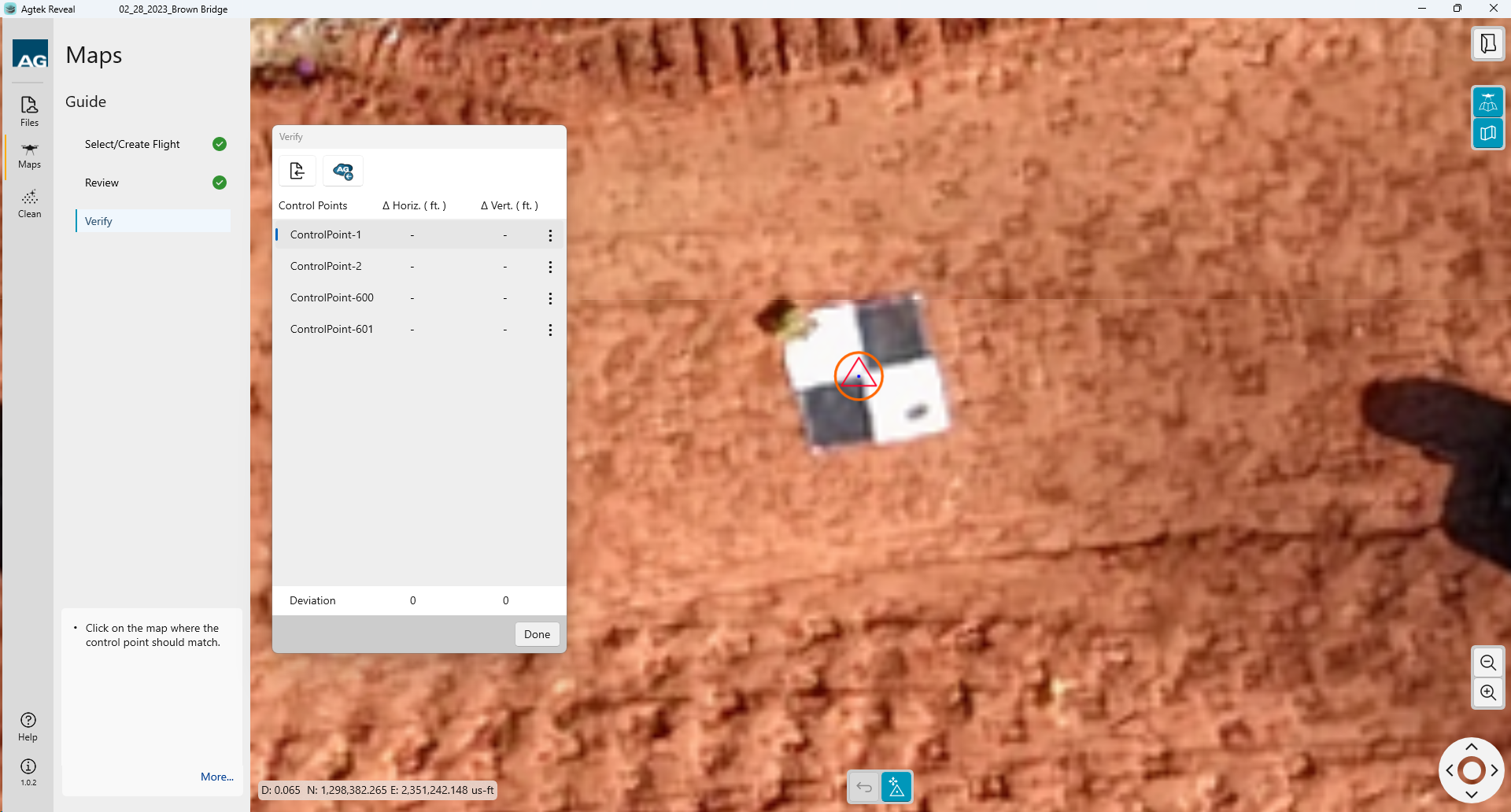
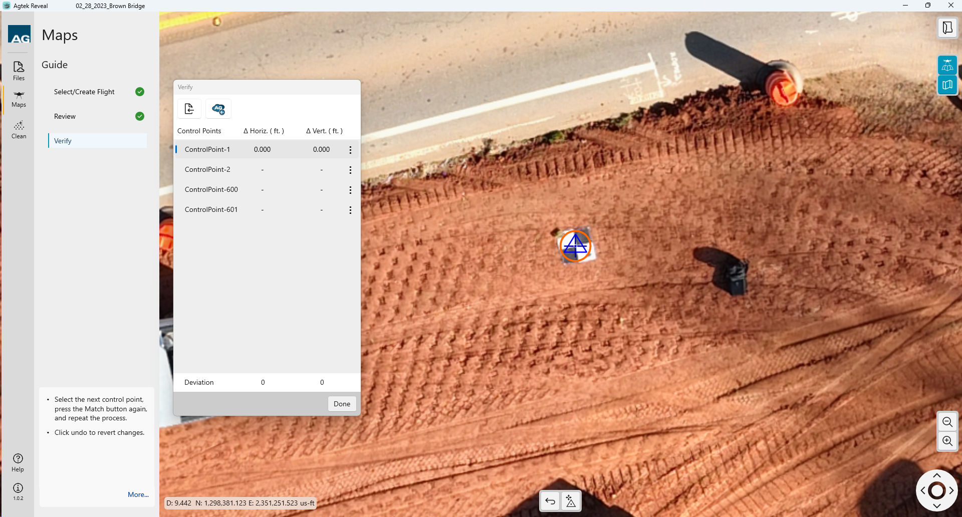
Match Point 1
Select the first point you wish to utilize as the Anchor point by left clicking on the benchmark symbol.
Select the Match
button ![]() at the bottom center of the
window.
at the bottom center of the
window.
The point will
show the symbol and be Red in color.
Left
click on the center of the control point marking on your site for
that point. The point symbol will turn Blue.
Match
Point 2
Navigate
to the next desired control point and select the point location as
shown in your point cloud or ortho. Left click to select. The symbol
will turn red.
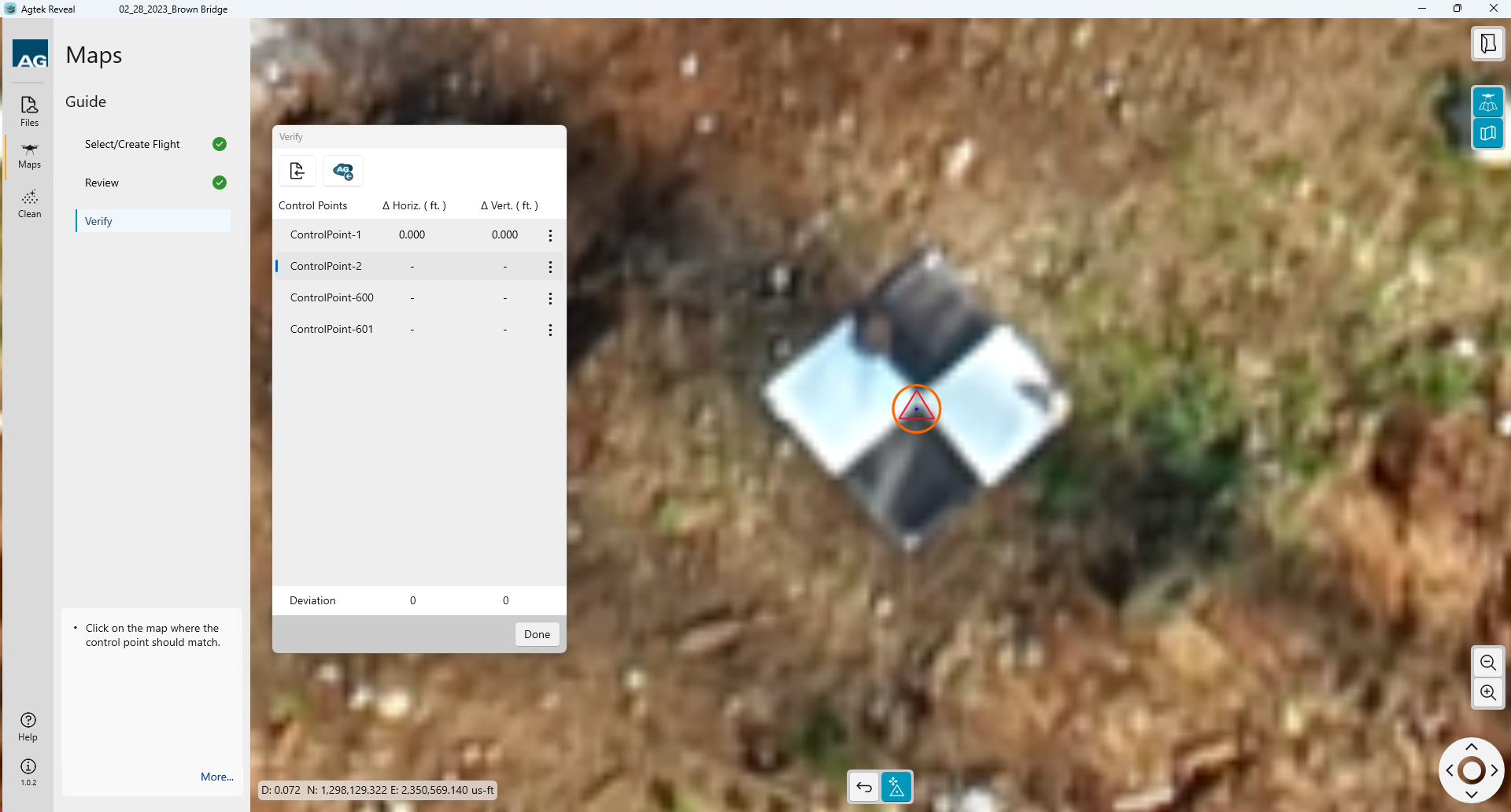
Left
click on the center of the control point marking on your site for
that point. The point symbol will turn Blue.
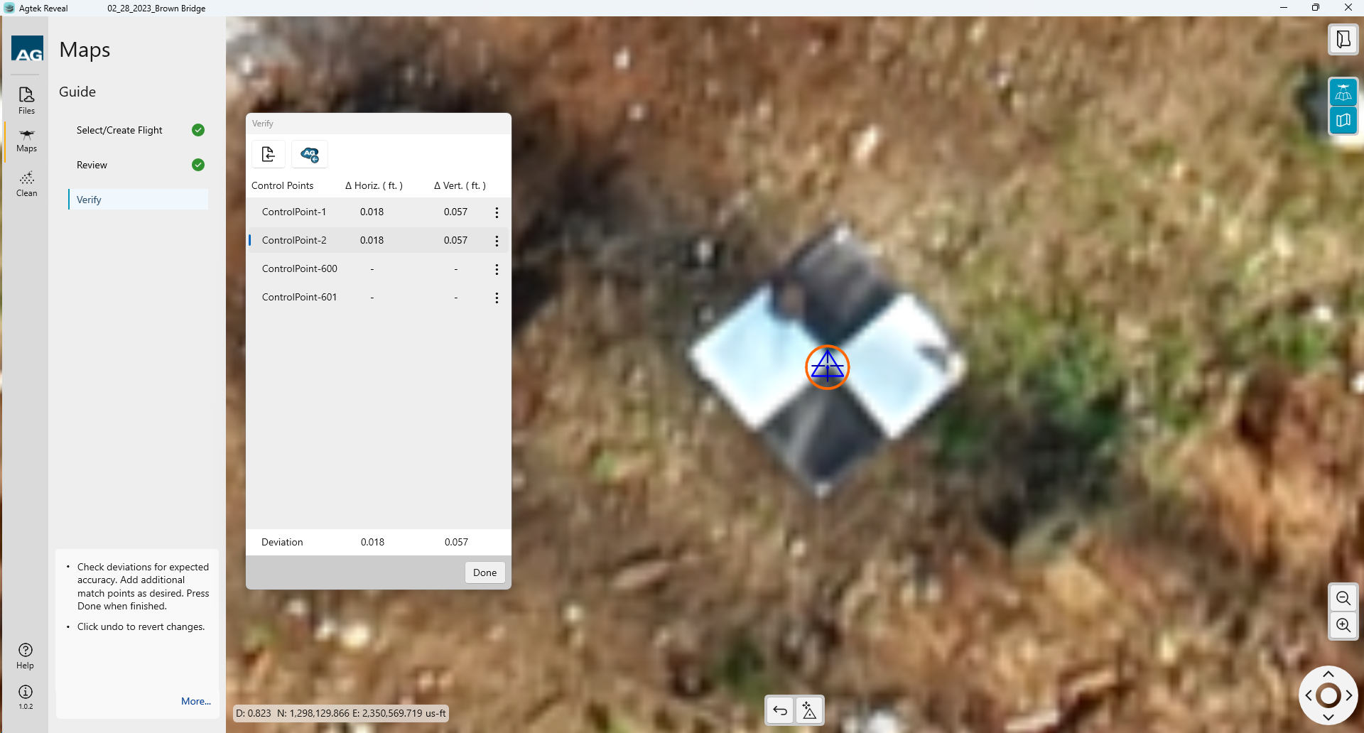
If
you need to adjust or go back a step you can click the Undo icon ![]() at the bottom of the window and repeat any of the above steps.
at the bottom of the window and repeat any of the above steps.
Enter any additional control points using the same procedure.
The Horizontal and Vertical deviations will be displayed. This verifies the alignment is correct.
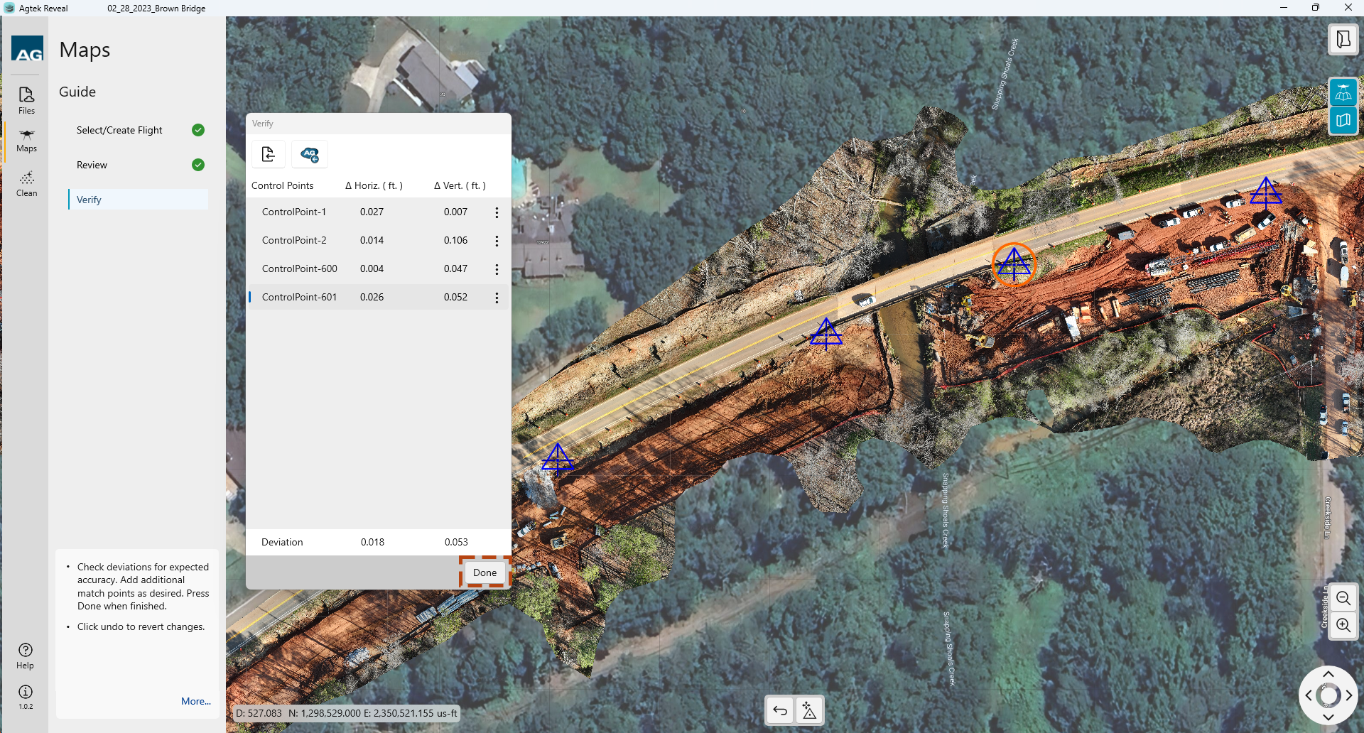
Once you have selected your control points for Verification, click Done.
After the point cloud has been registered, we can now clean up the classified data.
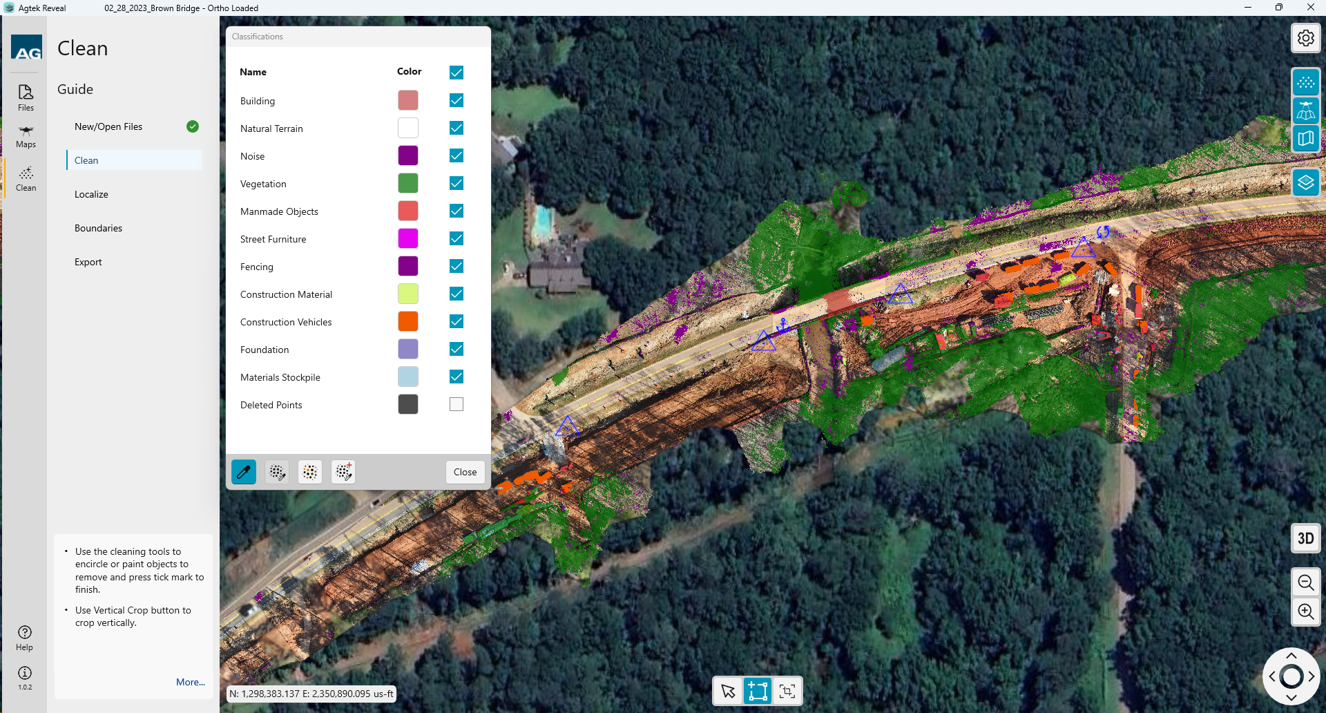
Click
the  button to view the 3D point cloud.
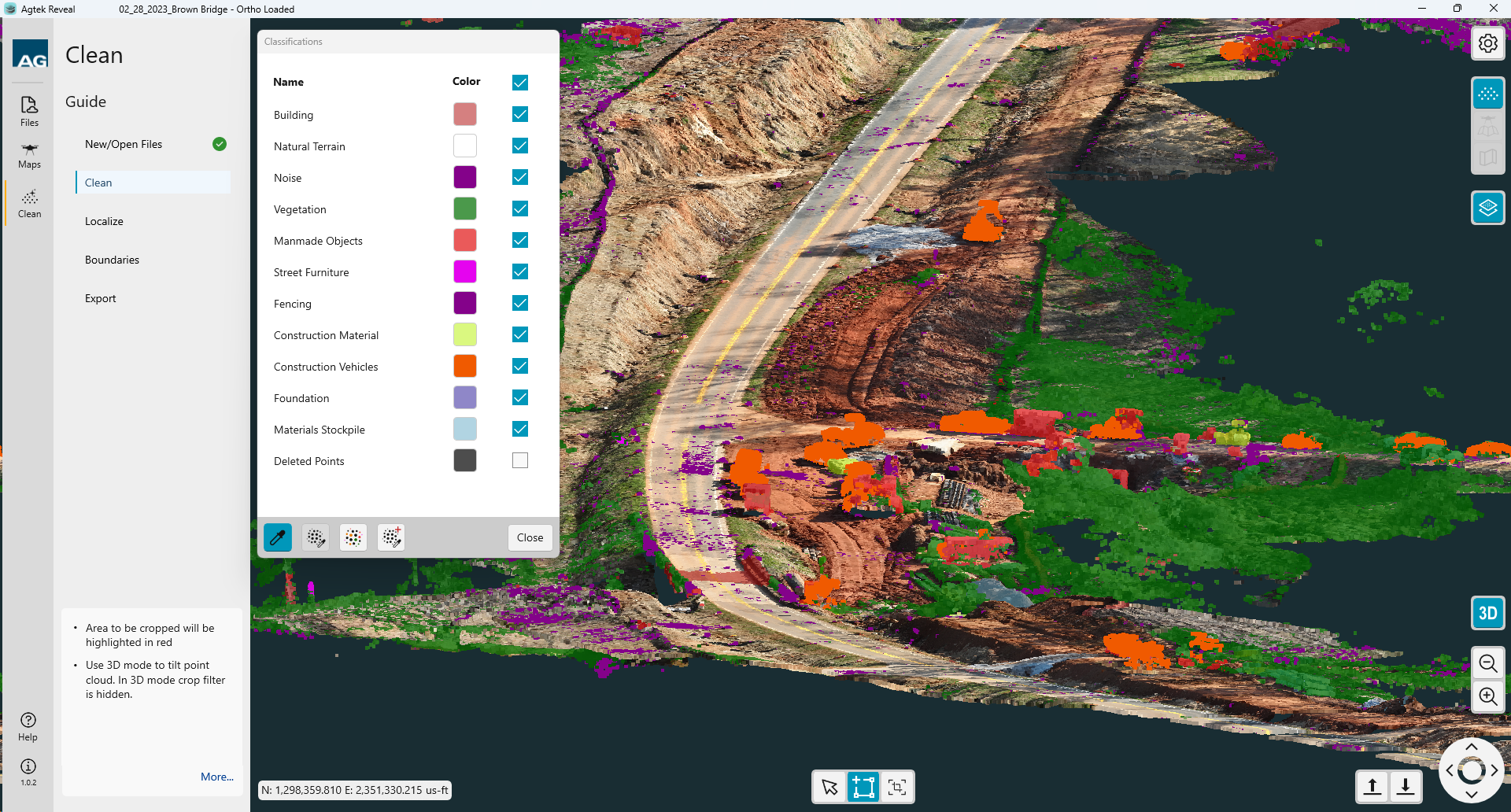
Note
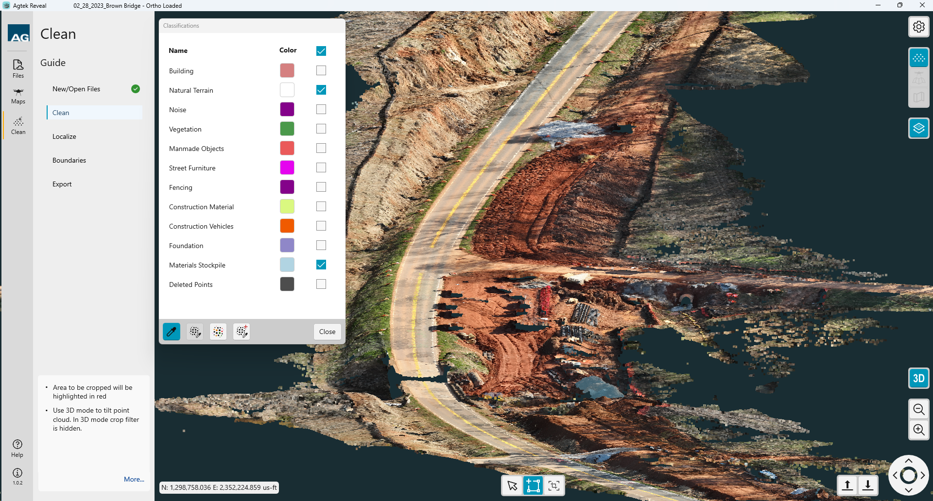
Check the box at the top to deselect all items. Check only the desired classified items.
After the classified items have been removed click Localize to continue with Registration.

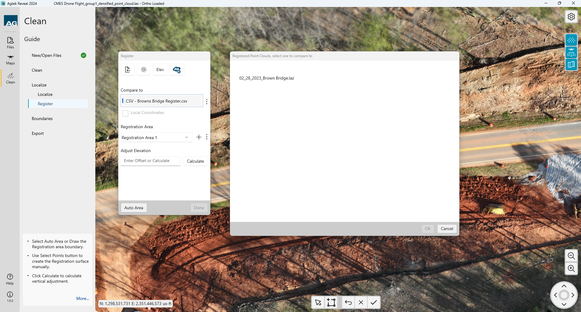
Register
Since we have completed the Localize (Verify) process in Maps, we can skip this step. Click Register.
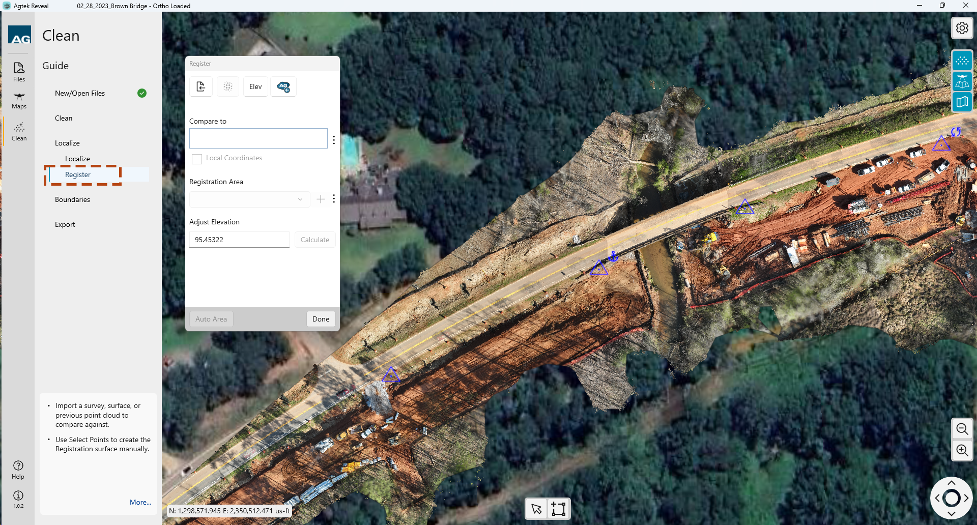
Begin by importing a registration file from your local device or Agtek Access.. The formats accepted are:
.adf
.csv
You
can also utilize another point cloud within your project by selecting
the Point Cloud Select  icon. This will allow you
to select from other point clouds within the active project.
icon. This will allow you
to select from other point clouds within the active project.
Once you have loaded your registration file or point cloud the points will be highlighted. You will need to create a boundary around your registration area. That can be accomplished by selecting the Auto Area button at the bottom of the dialog box or by drawing a boundary manually.
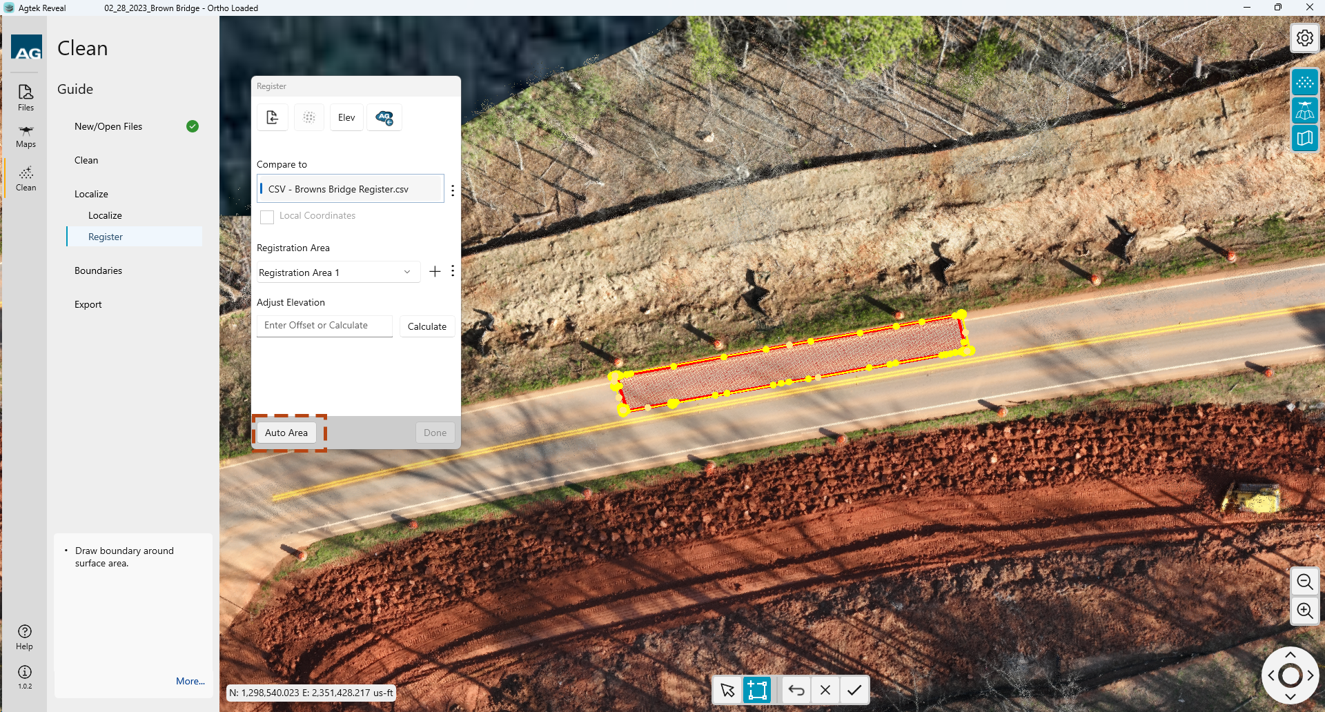
The Auto generated box can be adjusted by using the Selection tool and dragging the boundary nodes as needed. Create additional vertices by selecting the small nodes between.
ote:
Your Compare To: file name will be shown as well as the Registration Area you have selected.
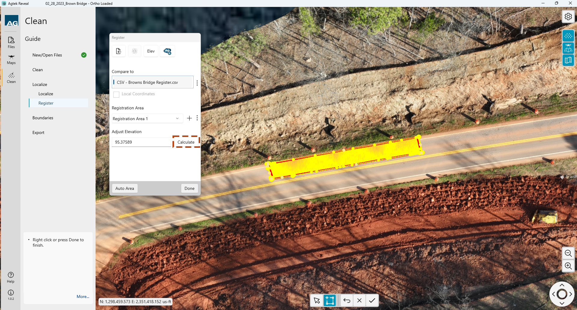
To run the Registration comparison select the Calculate button in the dialog.
To reset the calculated Registration, you can clear the elevation value and enter 0. No elevation adjustment will be made. Once complete select Done to continue.

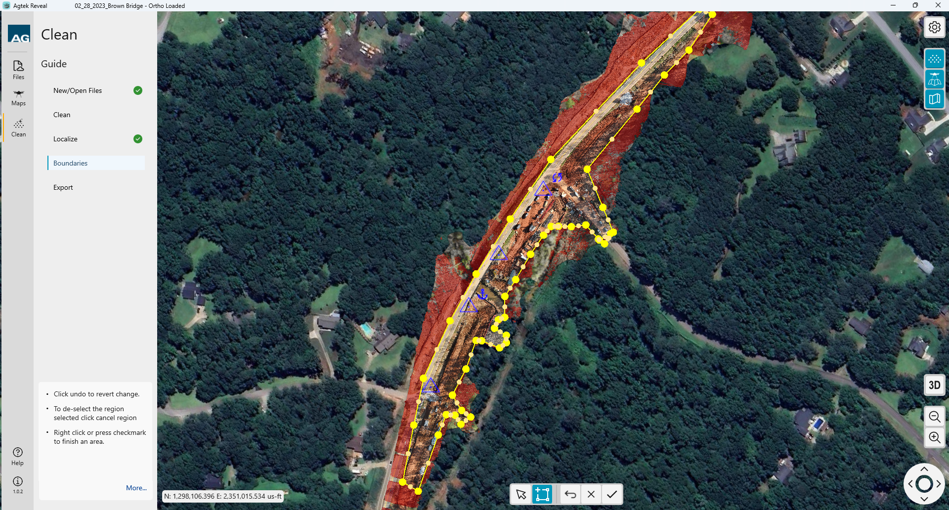
The next step in the process is to define the boundary or limits of your area of interest.
Left click to begin drawing your boundary.
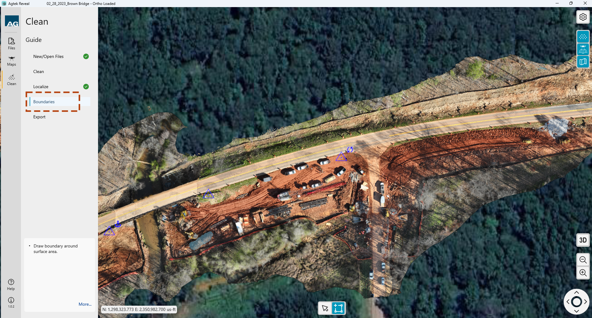
Close the boundary by right-clicking the mouse. or click the check mark button at the bottom of the screen.
 Edit
the perimeter boundary by selecting the Arrow icon at the bottom of the
screen, then click and drag the created points as desired..
Edit
the perimeter boundary by selecting the Arrow icon at the bottom of the
screen, then click and drag the created points as desired..
Additional points can be created by clicking on the midpoint between two existing points.
![]() At
any time you can click the Undo icon at the bottom of the screen to cancel
the last action.
At
any time you can click the Undo icon at the bottom of the screen to cancel
the last action.
 Once
the perimeter is complete and in the desired location, right click or
select the Check mark to complete.
Once
the perimeter is complete and in the desired location, right click or
select the Check mark to complete.
All highlighted points outside the defined Perimeter, shown in red. Those points will be accessible to you and can be reclassified if needed.
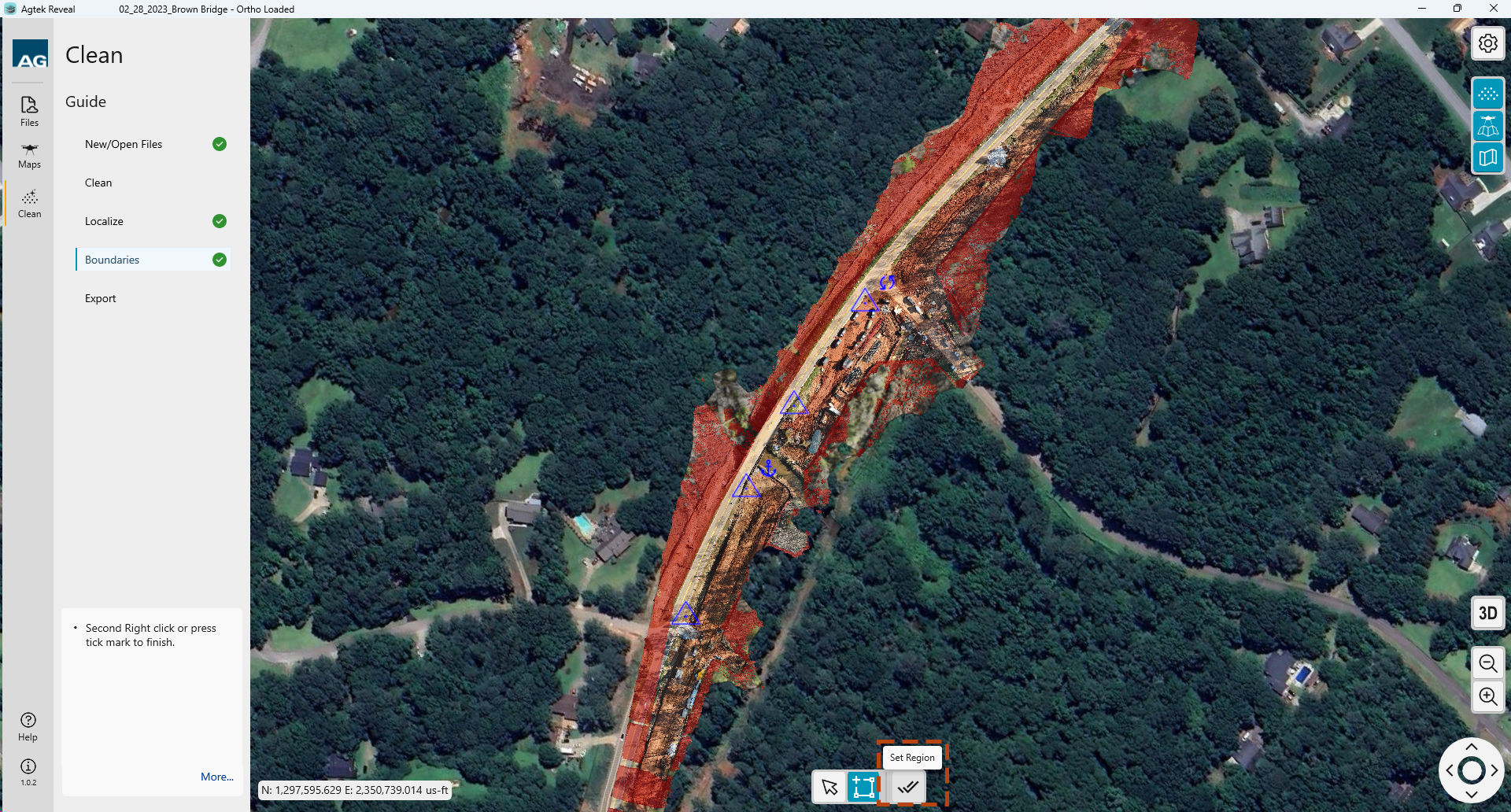
Complete your Boundary creation
by selecting the Set Region icon  . You
will then be directed to the Export options.
. You
will then be directed to the Export options.
Reveal allows you to export your optimized data sets to your local machine or directly to Agtek Access. Select the data you would like to include then the location icon you wish to save into.

When the export is complete, a message will display at the bottom of the export window.
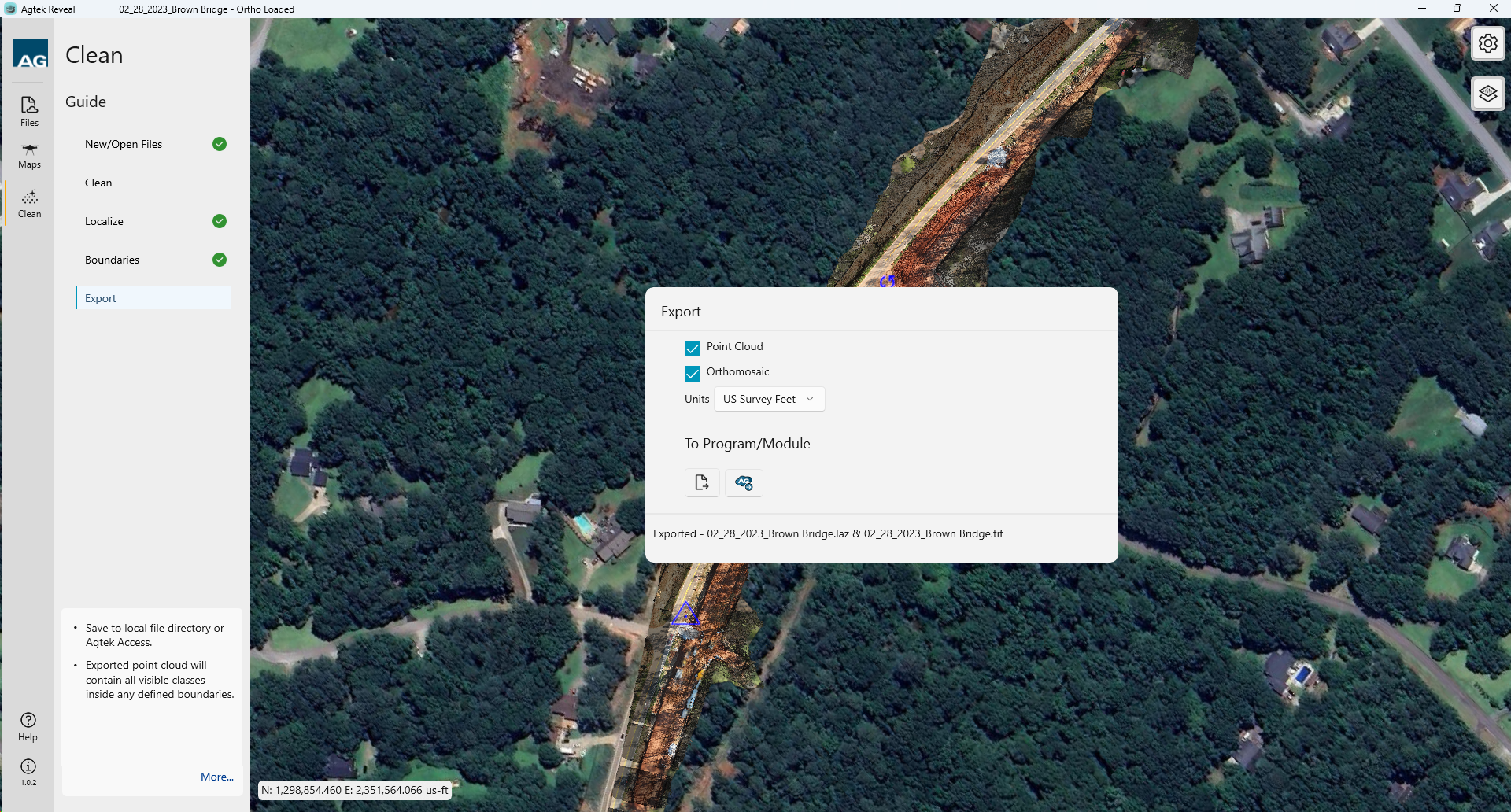
The export is complete.
Note: