The New Surface command allows the creation of additional surfaces. Seven unique surfaces can be added, however adding a subsequent surface causes the first surface to be replaced by the eighth. Each additional surfaces removes the last surface on the chain and replaces it with the one before.
![]()
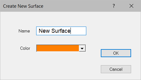
Select New Surface from the Utility menu in either Edit or Entry Modes. The following window displays.

The default name for the surface is "New Surface", but it can be changed by deleting the default name and typing a new one. You may also change the color of the surface data lines. Press OK to add the surface or Cancel to abort.
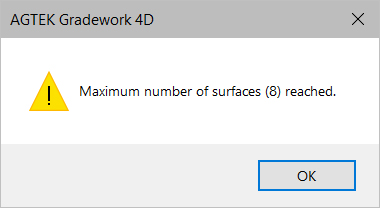
If more than eight additional surfaces are added, a warning displays the Maximum number of surfaces has been reached. You will need to delete one of the surfaces before adding a new one. Use Manage Surfaces to delete a surface. Click OK.

Press Yes to add the new surface and replace the surface listed above, or press No to abort adding the new surface.
![]()
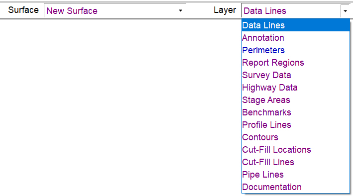
The layers of the first two new surface are not as extensive as other surfaces. Below are a list of the layers available on the first two new surfaces.

Data Lines |
Data Lines contain all the lines, points and labels. Data contained within this layer is used to generate the 3D surface. |
|
Annotation |
|
This layer is used to add reference line data that is not included in the surface trimesh calculation. |
Perimeters |
|
Perimeters may be added to all new surfaces to define the area to be calculated. |
Report Regions |
|
This layer is used to add Report Regions for volume calculations. |
Survey Data |
This is temporary data used with the Apply Survey command to stage the Survey Data to the Data Lines layer. |
|
Highway Data |
|
This layer is used if Highway data was generated. |
Stage Areas |
|
Data used to update the surface using Stage Over-Ex from the Over-Ex Guide. Once the data has been staged, the Stage Areas layer become empty. |
Benchmarks |
|
Contains any control points (Benchmarks) specified. These points are often used for re-scaling with grading plans or with AGTEK's Graphic Grade program |
Profile Lines |
|
Used to create profiles and cross sections across the job. |
Contours |
|
The Layer in which contours are created when using the Contour Surface command. |
Cut/Fill Labels |
|
These are spots entered to be used in conjunction with the User Cut-Fill Locations located under the View Menu in Planview Mode. |
Highway Data |
|
This layer contains any data generated by Highway mode. |
Cut/Fill Lines |
|
This layer contains any lines generated using the Cut/Fill Lines option. |
Pipe Lines |
|
The Pipe Lines layer contains any data entered as a Pipe Line in the file. |
Documentation |
|
Contains user added Notes or 3D Notes entered in Sitework 4D or Notes and Photos imported from SmartPlan. |